


-
You are here:
- Home
Yellow Room
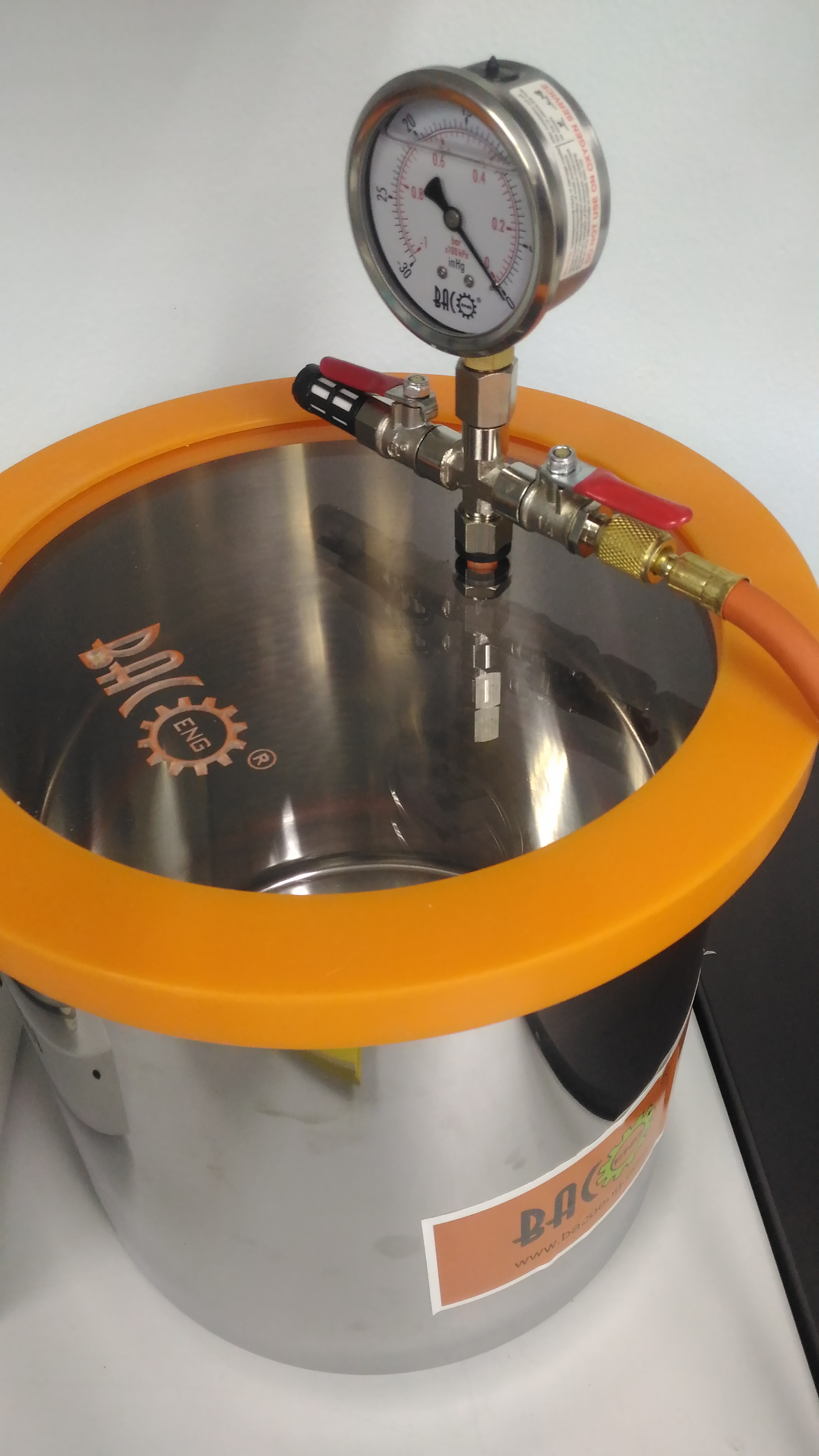
DEGAS VACUUM SYSTEM PIC : Syed Mohamad Syed Sahil Tel : +604-653 5641 Email : syed.mohamad@usm.my
GENERAL DESCRIPTION
Vacuum pump for removing trapped gases from compounds. With the appropriate vacuum pump degas chambers are used to reduce the pressure above the surface of the material and permit escape and subsequent removal of entrapped air and other gases that could induce failure of the final product. Degas chambers and pumps are available with several options and accessories for a complete vacuum degas system to meet user’s requirements.
SYSTEM FEATURES
- Anti-back flow
To prevent the oil from flowing back, preventing the container and the hoses from being polluted.
- Forced oil cycling system
The oil pump is forced lubricated by oil inlet system
- Integrated body structure
The pump body is structured by integral cylinder block, to achieve limiting vacuum
- Integral handle
The handle is firm and comfortable with high pressure rubber and metal insert.
- Big sight glass
With big sight glass, the oil level monitored clearly, preventing lack of oil.
- Large starting torque
This product could normally start under the circumstance of low temperature (≥-5˚C) and low voltage (≥180V) in winter
APPLICATION USED
- Degas Vacuum pump is used in the process to remove gases from compounds which become entrapped in the mixture when mixing the components.
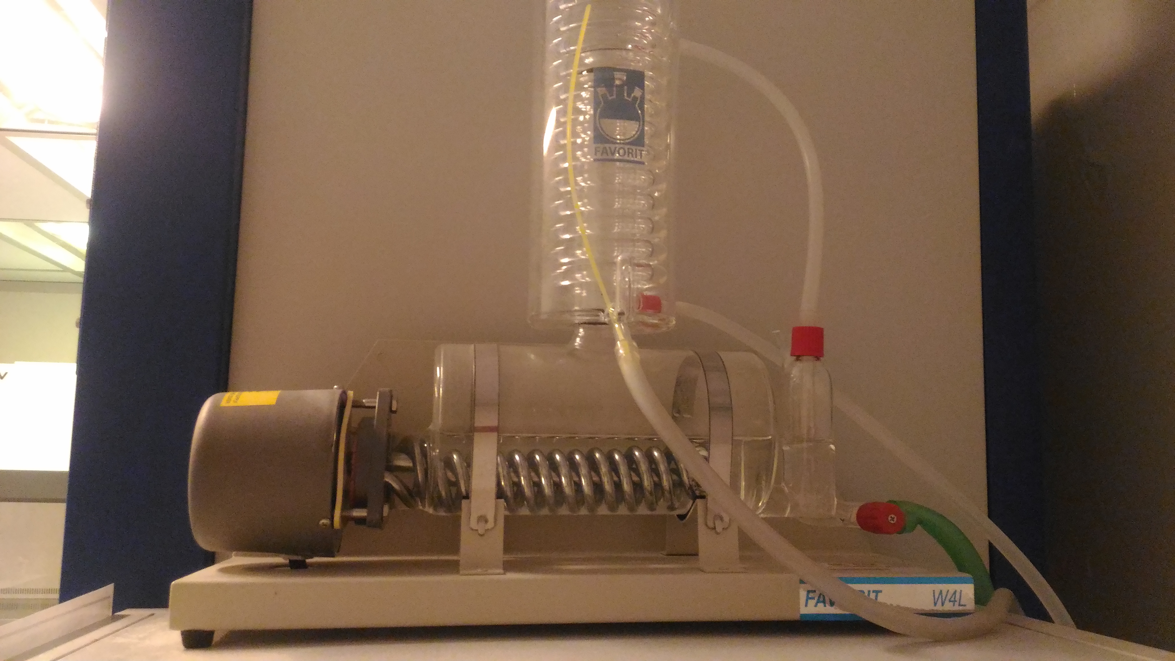
FAVORIT 4WL WATER STILLS PIC : Syed Mohamad Syed Sahil Tel : +604-653 5641 Email : syed.mohamad@usm.my
DESCRIPTION
Built-in constant level device with Vendura-Nova valve for drainage provides easy descaling without dismantling.
|
Distillate output |
4 litres per hour, single distilled |
|
pH |
5.0 to 6.5 |
|
Conductivity |
3.0 to 4.0 µs/cm |
|
Temperature |
35 to 50 ºC |
|
Pyrogen Content |
Pyrogen free |
SYSTEM FEATURES
Features
- Horizontal thick wall heat resistant borosilicate glass boiler fitted with 3 KW chromium plated heater.
- High efficiency coil condenser ensure low temperature, high output quality distillate of conductivity 3 to 4μs/cm.
- Compact construction suitable for bench and wall mounting.
- Screwthread connectors enable easy fitting or removal of hose safely.
- Built-in constant level device with Vendura-Nova valve for drainage provides easy descaling without dismantling.
- Safety thermostat built into the heater protect the Favorit water still in the event of water supply failure and automatically resets when the water supply is restored.
APLICATION USE
|
Distillate output |
4 litres per hour, single distilled |
|
Water Supply Requirement |
1 litre / min (Min pressure 3 p.s.i )(0.2 x 10⁵ NM-2) |
|
pH |
5.0 to 6.5 |
|
Conductivity |
3.0 to 4.0 µs/cm |
|
Temperature |
35 to 50 ºC |
|
Pyrogen Content |
Pyrogen free |
|
Power Requirement |
220/240v , 50/60 Hz single phase, 13A fused |
|
Dimension (d x w x h) |
50 x 15 x45 cm |
|
Catalogue Number |
P21001 |
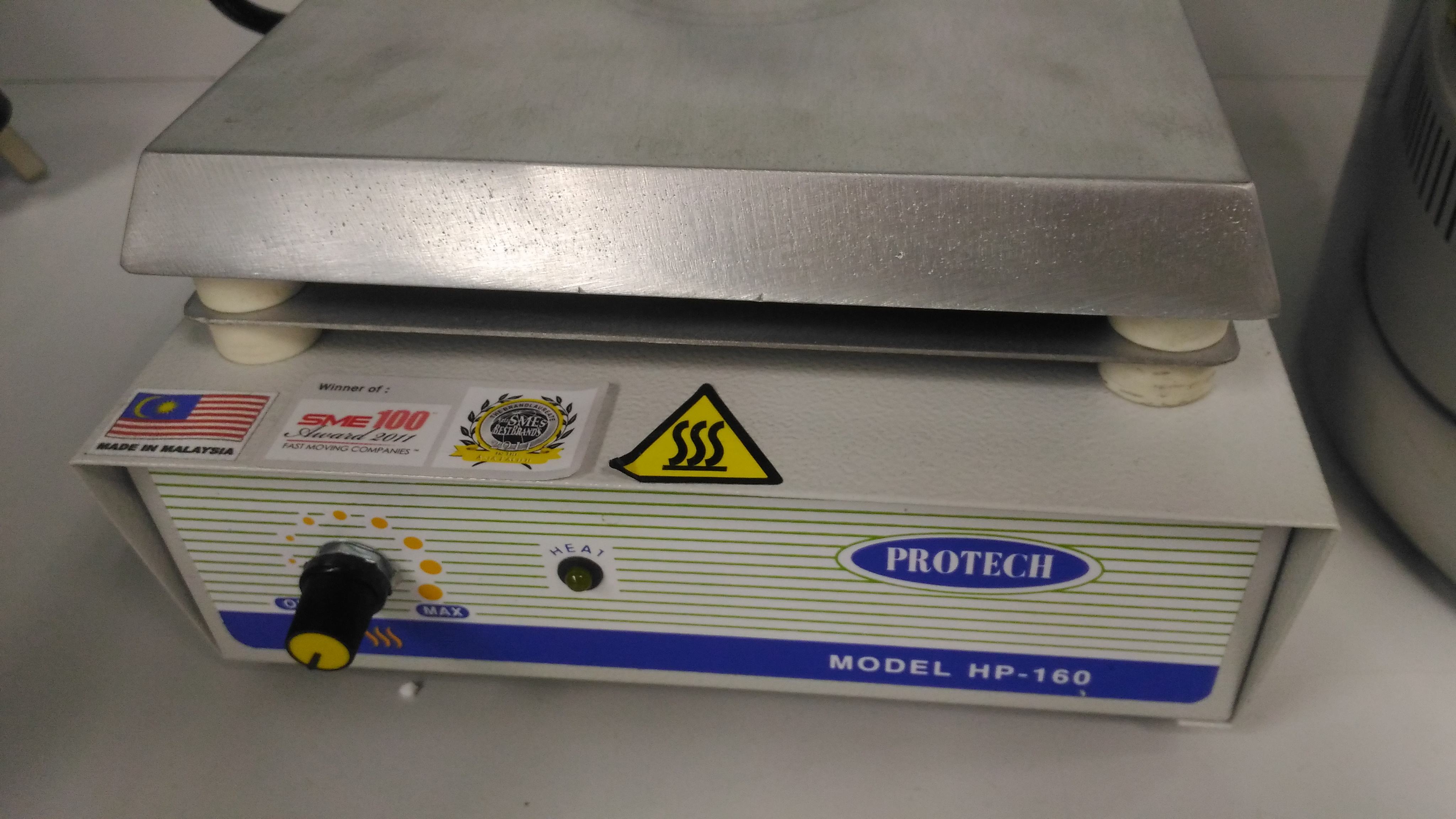
HOT PLATE FOR PHOTORESIST PIC : Rahil Izzati Mohd Asri Tel : +604-653 5681 Email : rahilizzati@usm.my
GENERAL DESCRIPTION
Hot plates are generally used to heat glassware or its contents. Hot plate top material is made by aluminium with dimensions 180 x 180mm. The temperature of hotplate can be up to 300˚C.
SYSTEM FEATURES
- Aluminium top plate provides maximum heat transfer and temperature uniformity.
- Perforated mild steel casing with baked enamel finish.
- With stepless adjustable electronic temperature controls providing excellent temperature stability.
- Heated top plates is situated remotely from all the working components by a layer of industrial insulation and metal plate. This ensure safe operation of the unit and a cool bench-top surface.
- For safe operation, the Protech Hot Plate include power indicator light that will illuminate when power is applied to the control. The hot plate has independent indicator light that illuminates when power is applied to the control.
- Excellent speed control up to 1300rpm is provided by speed control board.
- Supplied with a Teflon-coated stirring bar for stirrer model and a power cord.
APPLICATION USED
General laboratory heating and stirring
• Reagent preparation and heating
• Culture media preparation and heating
• Distillation, titration and evaporation procedures
• Sample drying
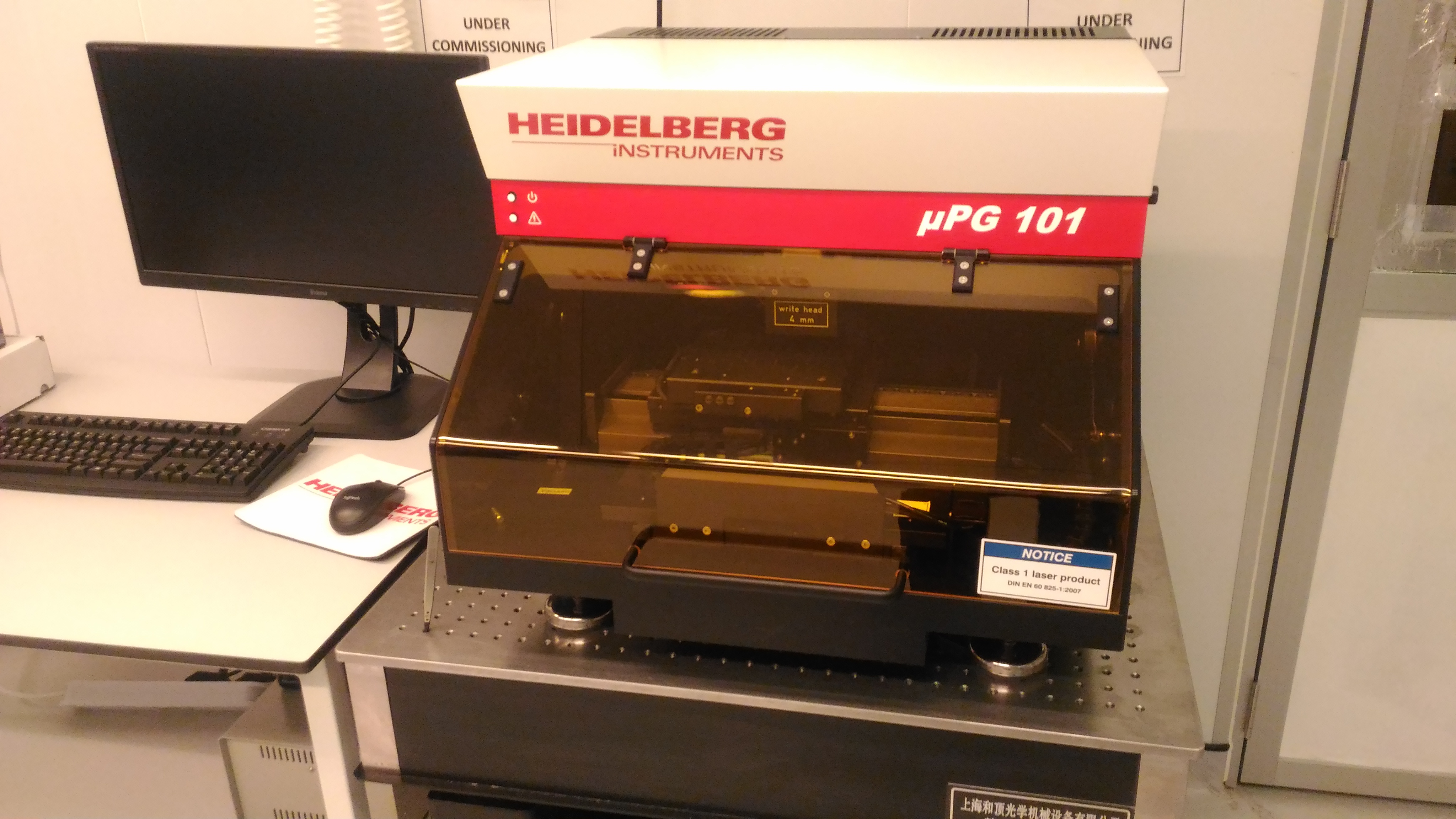
MASKLESS LITHOGRAPHY PIC : Rahil Izzati Mohd Asri Tel : +604-653 5681 Email : rahilizzati@usm.my
DESCRIPTION
Maskless lithography utilizes methods that directly transfer the information onto the substrate, without utilizing an intermediate static mask, i.e. photomask that is directly replicated. In microlithography typically radiation transfer casts an image of a time constant mask onto a photosensitive emulsion.
SYSTEM FEATURES
For typically small volume production of MEMS, MOEMS, fine feature PCB, high density chip packaging and display panels, especially for lab tests, low cost and the capability to change the original design easily and quickly are very important for customers and researchers. BALL Semiconductor Inc.'s Maskless Lithography Systems (MLS) feature the Digital Mirror Device (DMD) as the pattern generator to replace photo-masks. This can remove masks from UV lithography, and dramatically reduce the running cost and save time for lab tests and small volume production. At Ball Semiconductor Inc, 1.5μm line/space, 10μm line/space, and 20μm line/space Maskless Lithography Systems were developed. In our MLS, an 848×600 microlens and spatial filter array (MLSFA) was used to focus the light and to filter the noise. In order to produce smaller line-space than 16μm the MLSFA was used to get smaller UV light pad (compared with the SVGA DMD"s micro-mirror: 17μm×17μm) and to filter the noise produced from the DMD, optical lens system, and micro lens array. This MLSFA is one of the key devices for our Maskless Lithography System, and determines the resolution and quality of maskless lithography. A novel design and fabrication process of a single-package MLSFA for our Maskless Lithography System will be introduced. To avoid problems produced by misalignment between a two-piece spatial filter and microlens array, MEMS processing is used to integrate the microlens array with the spatial filter array. In this paper, the self-alignment method used to fabricate exactly matched MLSFA will be presented.
APPLICATION USE
For improved image resolution, ultraviolet light, which has a shorter wavelength than visible light, is used to achieve resolution down to around 100 nm. The main optical maskless lithography systems in use today are the ones developed for generating photomasks for the semiconductor and LCD industries.
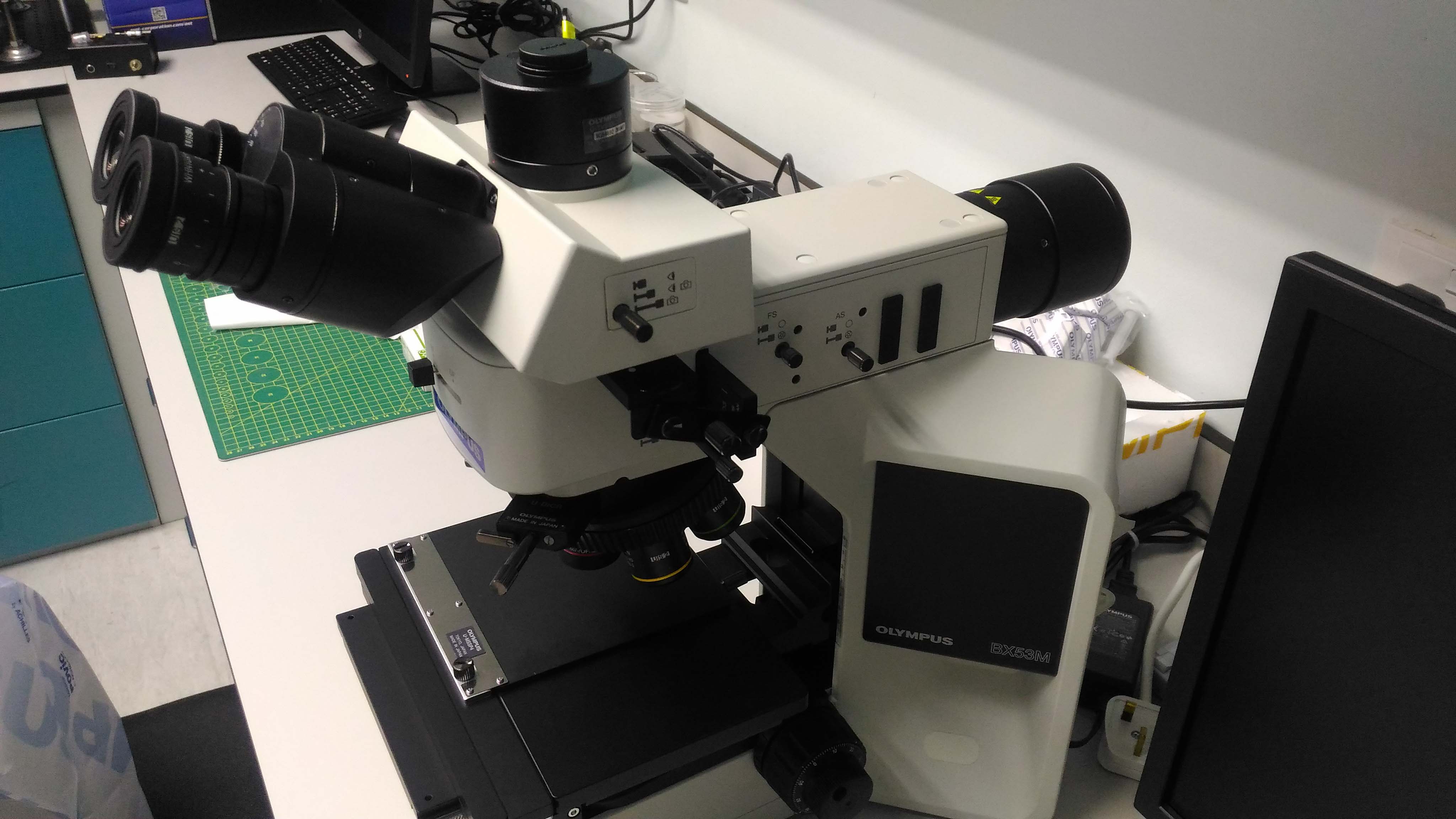
OPTICAL MICROSCOPE PIC : Nur Atiqah Hamzah Tel : +604-653 5681 Email : atiqahhamzah@usm.my
DESCRIPTION
The optical microscope, often referred to as the light microscope, is a type of microscope that commonly uses visible light and a system of lenses to magnify images of small objects. Optical microscopes are the oldest design of microscope and were possibly invented in their present compound form in the 17th century.
SYSTEM FEATURES
The optical microscope, also called the light microscope, uses a combination of light and lenses to magnify an image. Optical microscopes are used in the viewing of small objects such as cells. This type of microscope does not offer the highest magnification and so when viewing a cell has limited structures. For example in cells, organelles such as; lysosomes, the golgi apparatus, ribosomes and the cytoskeleton cannot be seen. The microscope cannot produce an image if the object has a smaller wavelenght than light. Cell components are usually transparent and so have to be stained to enable us to see them. It has developed over the years to maximize resolution and clarity with enhancements in technology allowing for a more precise image. The two types of optical microscopes are the simple microscope, which uses a single lens, and a compound microscope, which uses many lenses.
OPTICAL MICROSCOPE COMPONENT
Eyepiece
The lens at the top that you look through. It contains 2 or more lenses that focus the image. Usually has a 10x magnification.
Turret
This holds 2 or more objective lenses and can be rotated easily to change magnification power. Normally when viewing a slide for example, it is best to start the magnification at the lowest and then work your way upwards.
Objective
1 or more objective lens that collects light. The lenses are usually in a cylindrically shaped tube. The shortest lens has the lowest power i.e the lowest level of magnification, the longest one is the lens that has the greatest magnification power. The objective lenses usually have the magnification power 4x, 10x and 40x.
Focus wheel
These are wheels that move the stage in the vertical plane. There are also wheels for adjusting coarse and focus. Some microscopes however, do allow focus at the eyepiece as well.
Frame
The frame consists of the arm, the base and is in essence the bodywork of the microscope. It allows attachment of the focus wheels and the stage to the microscope.
Light source
A light source used in place of a mirror. Most microscopes do allow manual light adjustment via a wheel located near the base.
Condenser
The function of the condenser lens is to focus the light onto the specimen. To increase the quality the condenser lens may also have filters or a diaphragm.
Stage
A platform underneath the objective that provides a platform for the slide to be viewed. In the centre of the stage is a hole which allows light to pass through. The stage also normally has arms to hold the slide in place.
APPLICATION USE
This type of microscopy is used in microelectronics, nano physics, biotechnology and microbiology. It has allowed us to distinguish between different cells and their components, and also paved the way for the other types of microscopes which have enhanced how we view the human body and also in the fight against disease.
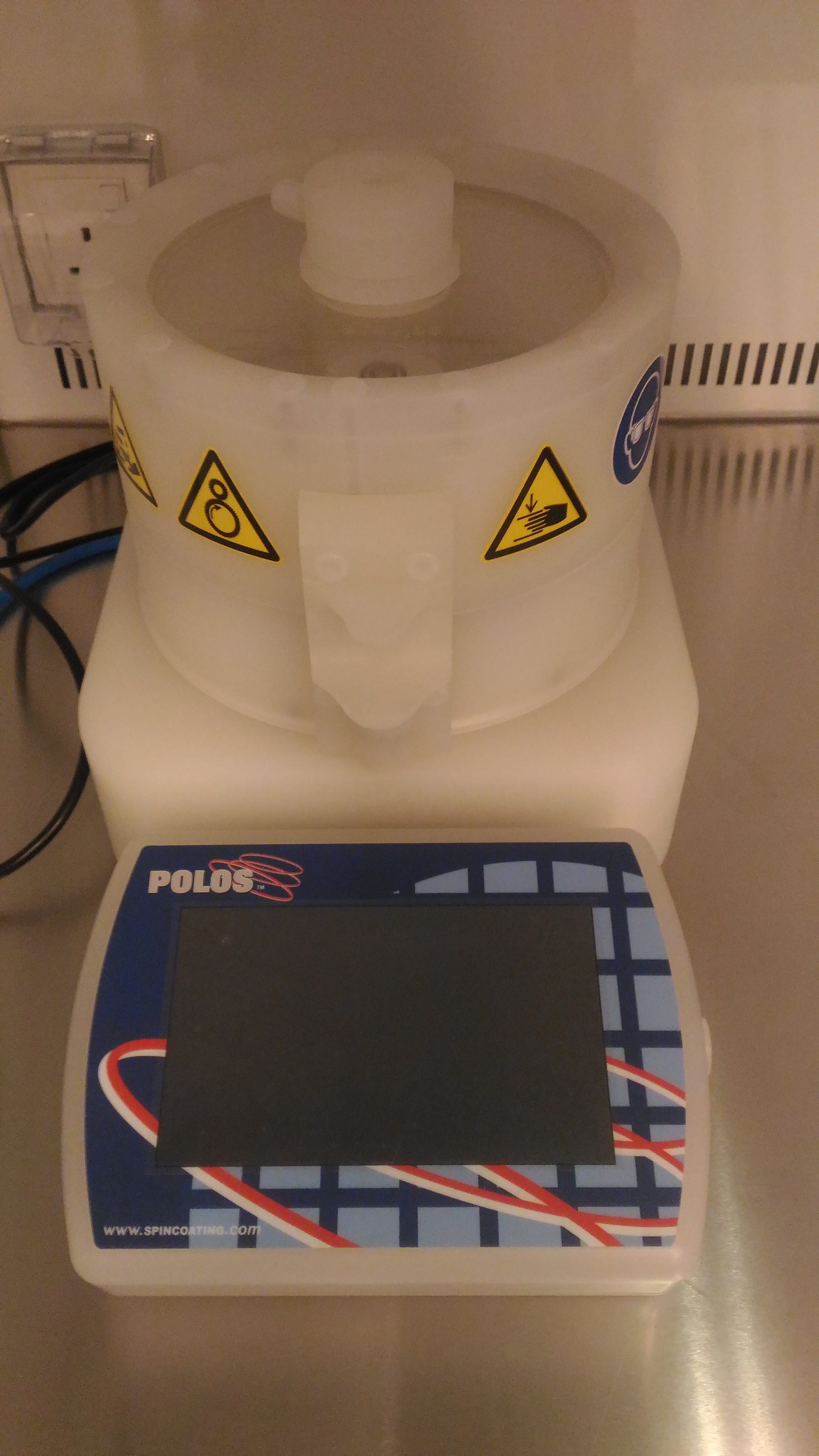
SPIN COATER PIC : Rahil Izzati Mohd Asri Tel : +604-653 5681 Email : rahilizzati@usm.my
 GENERAL DESCRIPTION
Spin coater system for the deposition of uniform thin layer specifically for photoresist,which is essential for photolithography process.
SYSTEM FEATURES
- Comply and better,the spin coater system has spin speed of 0-12000 rpm in less than 1 sec.
- Comply and better,spin acceleration and deceleration of 1-13000 rpm/sec selectable per step.
- Comply and better, central dispensing syringe holder consist of a maximum of 3 syringe holder.
- Comply and better,spin 150i comes with a vacuum pump for substrate chuck suitable for various dimension from 0.5 inch(1cm) 2 inch (5cm) up to 6 inch(15cm) diameter sample size.
- Comply and better,the chuck can accommodate various dimension from 0.5 inch (1cm) 2 inch(5 cm) up to 6 inch (15cm) diameter sample size.
APPLICATION USE
Spin coating can be used to create thin films of less than 10nm thickness. Spin processing can be used for cleaning or etching. Most substrates can be spin processed, including wafers, microscopeslides, photomasks, or even small pieces etc.